Blinker
 You may have seen these things before:
Infrared beacons have been popping up in various 'modern warfare' video games for years now, and I always figured that they were a microcontroller or a 555 timer chip with a battery and IR LEDs. Turns out I was pretty much on the money: according to this article from Wired the devices in the photos above are infrared beacons probably produced by a company called Cejay Engineering. A quick browse of the website yields some interesting technical details and the images of the devices pretty much confirm my suspicions regarding construction. I have no idea if operators actually use these specific devices as personal beacons (I doubt it - these don't look nearly robust enough, and if these were the only thing separating me from a burst of 25mm shells from an AC-130, I'd want something that had more positive locking to the power supply) but the Wired article describes these things issued as disposable ('throwable') markers issued to friendly natives for the purpose of marking targets. Cheap, reasonably robust, nearly impossible to screw up, and don't contain sensitive technology.
I immediately wanted some, even though I don't have any night-vision equipment or need to mark myself or airstrike targets.
The 25USD price tag noted in the Wired article seemed a bit outlandish so I set about making my own.
555 timers are neat little thingamajobbers. I've made microcontroller timers in the past but surprisingly have never mucked around with these guys at all.
The 555 timer has two modes of operation: monostable and astable.
In monostable mode, the IC will output a pulse of some duration when triggered. Why is this useful? The 555 can detect a noisy signal and output a much cleaner signal for almost any desired duration. This is useful if you want to provide a clean signal from a button (commonly referred to as 'debouncing' a button), or if you're trying to wire a cell phone speaker to an electric blasting cap.
(Yes, I know that's not actually a 555 IC on that device. Theory is sound, though.)
It can also be used to make a simple timer to tell you when the coffees ready. You know, whatever.
Astable is basically the same, except the IC is rigged to reset itself and thus it produces a constant and continuous waveform. Tweaking component values will adjust the period and duty cycle.
STMicroelectronics NE555N Timer IC (datasheet, local copy)
LiteOn LTL2R3SEK-002 LED (datasheet, local copy)
Couple of common resistors
Couple of common capacitors
The circuit is a direct copy of the astable circuit in the 555 datasheet:
That is a bit of a mess, so here is a simplified wiring diagram:
Note the orientation of the LEDs. The circuit presented here cannot produce duty cycles (i.e. time that the output is held high) of less than 50% of the period (time that the output is held low plus time that the output is held high). I wanted a duty cycle that was significantly less than 50% of the period. Fortunately the 555 (or at least this one) can source or sink up to 200mA of current. I flipped the polarity (eat it Star Trek!) of the LEDs and adjusted my math. I wanted a duty cycle of 0.4 second with a period of 2 seconds (0.4 seconds off-time and 1.6 seconds on-time). Honestly, I'm not sure where I picked up those numbers. The specs pages for Cejay Engineering's Phoenix Junior and Pegasus markers lists a duty cycle of 0.02 seconds and a "flash repeat cycle" of 1.3 seconds.
Speaking of math, the datasheet also came with a number of equations to be used to calculate period and duty cycle of the circuit given resistor and capacitor values, and visa-versa.
	Tl = ln(2) * R2 * C
	Th = ln(2) * (R1 + R2) * C
	f = 1 / ln(2) * C * (R1 + (2 * R2))
According to figure 17 in the NE555 data sheet, 100uF caps are probably the best choice for my purposes:
	Tl = ln(2) * R2 * 0.0001F = (2s - 1.6s)
	R2 = 0.4s / ln(2) * 0.0001F = ~5770.78 ohms

	Th = ln(2) * (R1 + 5770.78 ohms) * 0.0001F = 1.6s
	R1 = (1.6s / (ln(2) * 0.0001F)) - 5770.78 ohms
	R1 = ~17312.34 ohms
Problem: Those are some weird resistor values. Let's work backwards from resistors I know I have:
	R2: Tl = ln(2) * 5110 ohms * 0.0001F = 0.354198209s
	R2: Tl = ln(2) * 6810 ohms * 0.0001F = 0.47203323s
That last one (6810 ohms) looks good. Always thought 400ms was a bit short.
	R1: Th = ln(2) * (6810 ohms + 12100 ohms) * 0.0001F = 1.310741318s
	R1: Th = ln(2) * (6810 ohms + 21500 ohms) * 0.0001F = 1.962299668s
So, using a 6810 ohm and a 12100 ohm resistor with a 100uF cap I get a period of ~1.78 seconds.
Since there is 9 volts from supply and 200mA sink capability we can string a number of LEDs in series on the output. In fact I recommend it: the LEDs I'm using have a typical forward voltage of 2.25 volts:
	R = V/I
	R = (9 volts - 2.25 volts) / 0.050
	R = 135 ohms

	P = IV
	P = (9 volts - 2.25 volts) * 0.050
	P = 0.3375 Watts
To drive one at 50mA I'd need a 135 ohm resistor and that would dissipate about 0.34 watts. I'd much rather throw in some more LEDs instead of dumping power as heat via a large resistor.
Interestingly, four times 2.25 volts is 9 volts even - that almost looks like it was planned. This is perfect, except that the voltage of the battery will drop with use. As soon as the voltage from the battery drops below 9 volts the forward voltage of the LEDs is no long met and none of them will light.
The 555 will cut out at 4.5 volts which is approximately the forward voltage of two LED in series. How does that look?
	R = V/I
	R = (9 volts - (2*2.25 volts)) / 0.050A
	R = 90 ohms

	P = IV
	P = 4.5 volts * 0.050A
	P = 0.225 Watts
So a 90 ohm resistor will limit current to 50mA, assuming 9 volts minus the voltage drop of two LEDs. Power dissipation comes in at 0.225 watts, just a hair under a quarter watt - one of the more widely available resistor wattages. I happen to have a bunch of 100 ohm 1/4 watt resistors - these won't provide a full 50mA but that was the absolute maximum rating anyway. In this configuration the LEDs will lose brightness as the battery voltage drops, but they won't go out until about the time the 555 chip shuts down.
So how does it all look when put together?

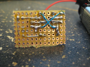

Really fucking bright, thats how it all looks when put together. For once my photos do LEDs justice.
Hacking off a chunk of and wiring up a perf board every time I want to make one of these is a kind of a pain. I may spend a wad of cash to make a bunch of boards for these.
Converting it to a surface mount kit would be trivial (says the guy who does that kind of thing for a living) but I don't see any particular advantage. Well, unless I buy a pick-and-place machine or get these manufactured professionally.
DISCLAIMER
All content is owned by its respective creators/licence holders.
Unless otherwise stated, everything else: Copyright © 2009-2011, Chlazza